


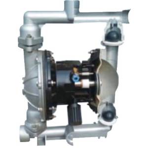
Air Operated Double Diaphragm Pumps
Request QuoteAODD PUMPS
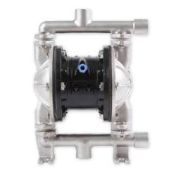
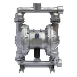
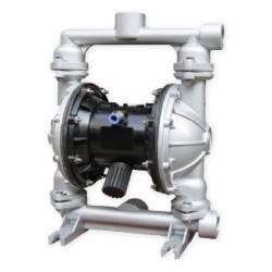
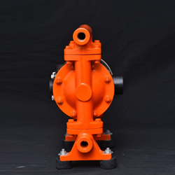
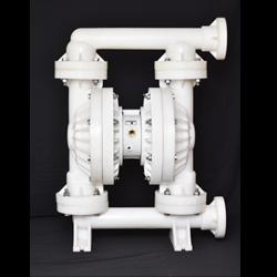
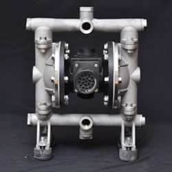
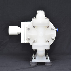
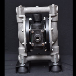
AODD Pumps (Air Operated Double Diaphragm Pumps) If your industry needs transfer applications frequently and handles different types of feeds, like slurries, sludges, shear, abrasive, and sensitive fluids, you should install a type of positive displacement pump. Here comes the role of AODD Pumps, which are robust and reliable. These pumps consist of two different pumping chambers, which fill alternatively and discharge via flexible diaphragm movement.
The design of Air Operated Double Diaphragm Pumps is according to an air valve located inside the central chamber of the pumps. Air enters the air valve and directs it to a particular side of the diaphragm to create a vacuum on one side and compress the air diaphragm on the other side. Delivery manifolds, suction, central air valve, diaphragms, seats, and balls are primary parts of the diaphragm of AODD pumps. These components perform their functions similarly to valves inside the pump.
Whenever the inside of the pump creates a vacuum in its one diaphragm, it rises the balls on its suction side from the seats to let the fluid enters the diaphragm. Simultaneously, balls close to the pump's discharge manifold seal against the pump seats. In the compressed opposing diaphragm, fluid will push the ball against its seats close to the manifold of the suction, and the discharge manifold balls will not seal the outlet. Accordingly, the fluid expels from the discharge manifold to repeat the cycle continuously.
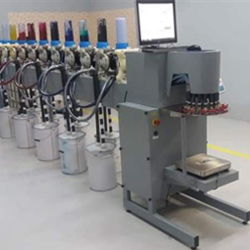
Air Operated Double Diaphragm Pumps are useful as front-step transmission systems of any liquid and solid separation device. These pumps are also useful to suck grinding materials, glazed slurries of porcelain and tiles, paint materials, glue, pigment, adhesives, and various types of flammables. AODD pumps may even suck toxic, corrosive liquids, strong acids, and volatile liquids. Other common applications of the pump are sucking tomato slurry, peanuts, pickles, chocolates, red sausages, syrups, and hops.
Precision Engineering Co are the one of the best AODD Pumps manufacturer, AODD Pumps
exporter and AODD Pumps supplier in Mumbai, India. We are the cover the pan india to best
deilver our AODD Pumps product. If you have this product please wuote here!
Precision Engineering has launched AODD Pumps that have been developed with the most advanced technologies of our times. Alongside simple usage, we have even ensured the safety of our customers. Compared to other machines, our AODD Pumps techniques are
efficient in managing work-hour capacity and enhancing productivity. Alongside high
production value, our pump go low on maintenance.
Precision Engineering company air operated double diaphragm pumps (AODD pumps) are designed for general fluid transfer. Our diaphragm pumps reliably transfer a wide variety of fluids, from clean, light viscosity to medium viscosity. They can pump large particles without damage.
- Top quality
- Reasonable
- Longer Life
- Rigid Design
- Easy to Use
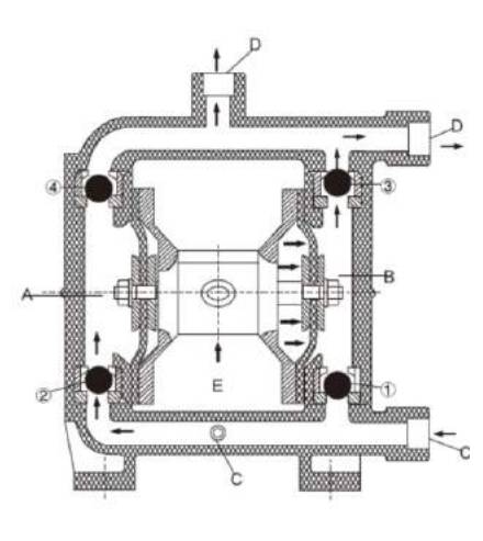
WORKING PRINCIPLES
There installs each diaphragm in both aligned working cavities (A) & (B), which can be connected together with a central coupling lever. The compression air enters the air distribution valve from the air entrance of the pump, draw the compression air into one cavity through the air distribution mechanism, push out the diaphragm movement in the cavity. The gas in another cavity will be drained.
Once reaching the stroke terminal, the air distribution mechanism will automatically draw the compression air into another working cavity, push out the diaphragm to move towards the opposite direction, so as to let the both diaphragms continuously reciprocate motion in synchronism.
The compression air enters the air distribution valve from (E) shown as the diagram, let the diaphragm piece move towards the right direction. And the suction force in (A) chamber lets the medium flow into from (C) entrance, push out the ball valve (2) to enter (A) chamber, the ball valve (4) will be locked due to the suction force; The medium in (B) chamber will be pressed, push out the ball valve (3) to flow out from the exit (D). Meanwhile, let the ball valve (1) close, prevent backflow. Such movement in circles will let the medium uninterruptedly suck from (C) entrance and drain from (D) exit.
Working Principles
MAIN USAGE
The pump can suck the peanut, pickles, tomato slurry, red sausage, chocolate, hops and syrup etc.
The pump can suck the paint, pigment, glue and adhesive etc.
The pump can suck various glazed slurries of tile, porcelain, brick and chinaware etc.
The pump can suck various grinding materials, corrosive agent and clean the oil dirt etc.
The pump can suck various toxin and flammable or volatility liquid etc.
The pump can suck various wedge water, cement slurry and mortar etc.
The pump can suck various strong acid, alkali and corrosive liquid etc.
It can be used as a front-step transmission device of the solid and liquid separation equipment.
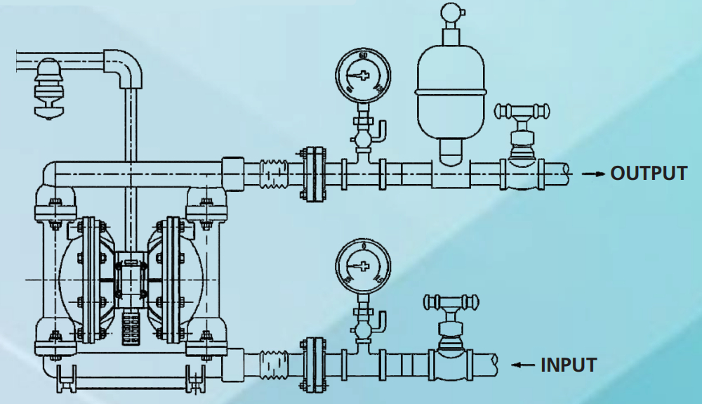
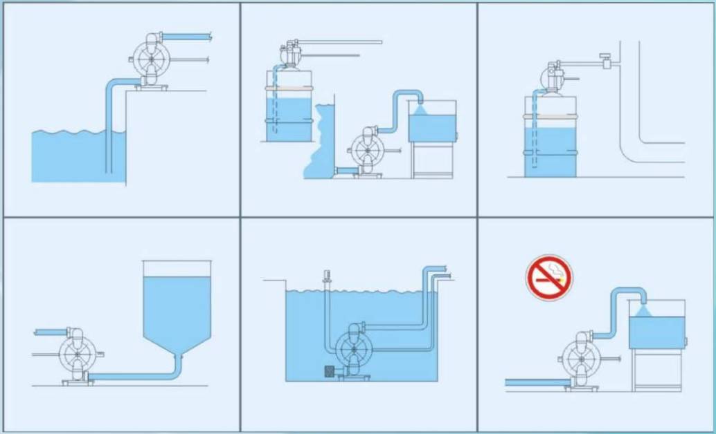
SYSTEM CONNECTION SCHEMATIC DIAGRAM
QBY - K8
QBY-K10/15
QBY-K25
QBY-K40
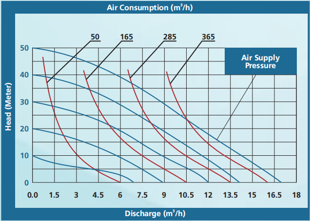
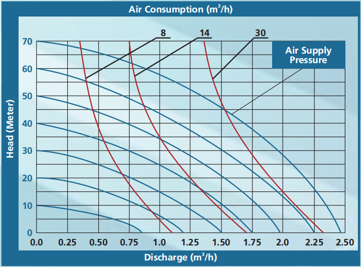
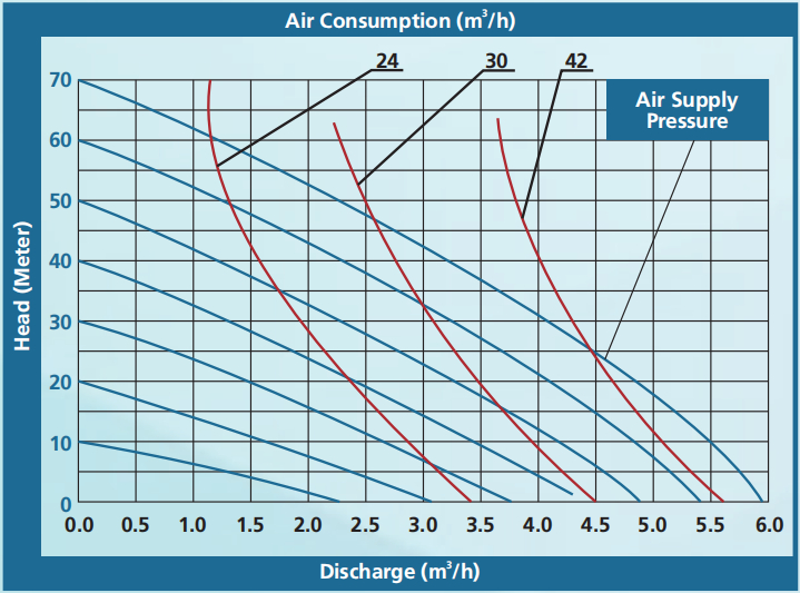
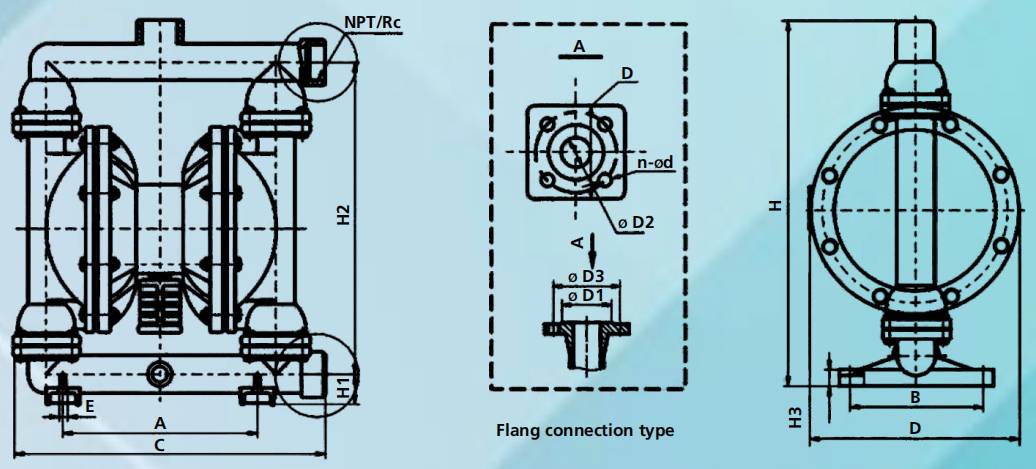
DRAWING OF SETTING DATA
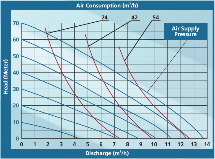
PUMP SPECIFICATION
Total Discharge Head (Meter)
| Model | A | B | C | D | E | H1 | H2 | H3 | H | Screw | Flange | ||||||
| NPT/RC | D1 | D2 | D3 | D | n | d | |||||||||||
| QBY-K8 | 97 | 84 | 147 | 115 | 7 | 20 | 110 | 10 | 143 | 3/8 | - | - | - | - | - | - | |
| QBY-K10/15 | 130 | 50 | 220 | 145 | 10 | 39 | 195 | 10 | 270 | 1/2 | - | - | - | - | - | - | |
| QBY-K25 | 245 | 160 | 360 | 250 | 12 | 63 | 36 | 360 | 470 | 1 | - | - | - | - | - | - | |
| QBY-K40 | 245 | 160 | 360 | 250 | 12 | 63 | 360 | 35 | 470 | 11/2 | - | - | - | - | - | - | |
| QBY-K50 | 335 | 220 | 540 | 345 | 16 | 88 | - | 25 | 720 | - | 90 | 50 | 110 | 130x130 | 4 | 14 | |
| QBY-K65 | 335 | 220 | 540 | 345 | 16 | 88 | - | 25 | 720 | - | 110 | 65 | 130 | 130x130 | 4 | 14 | |
| QBY-K80 | 425 | 250 | 570 | 450 | 18 | 110 | - | 32 | 900 | - | 125 | 80 | 150 | 160x160 | 4 | 18 | |
| QBY-K100 | 425 | 250 | 570 | 450 | 18 | 110 | - | 32 | 900 | - | 145 | 100 | 170 | 160x160 | 4 | 18 | |
PERFORMANCE PARAMETER
| Model No | Discharge (m3h) |
Head(m) | Exit pressure (kgf/cm2) |
Sucked lift(m) | Max. gain Dia(mm) | Max. Pressure (kgf/cm2) |
Max. air consumption (m3min) |
(m3/min) | |||||
| ZL104 | 1Cr18 Ni9Ti |
HT200 | Enhanced Polypropylene |
Fluorin-lining in filtrated part F46 (EFP), PO | |||||||||
| QBY-K8 | 0~0.8 | 0~50 | 6 | 5 | 1 | 7 | 0.6 | 0.3 | ★ | ★ | ★ | ★ | / |
| QBY-K10/15 | 0~1 | 0~50 | 6 | 5 | 1 | 7 | 0.6 | 0.3 | ★ | ★ | ★ | ★ | / |
| QBY-K25 | 0~2.4 | 0~50 | 6 | 7 | 2.5 | 7 | 1.7 | 0.6 | ★ | ★ | ★ | ★ | ★ |
| QBY-K40 | 0~8 | 0~50 | 6 | 7 | 4.5 | 7 | 1.7 | 0.6 | ★ | ★ | ★ | ★ | ★ |
| QBY-K50 | 0~12 | 0~50 | 6 | 7 | 8 | 7 | 4.9 | 1.7 | ★ | ★ | ★ | / | ★ |
| QBY-K65 | 0~16 | 0~50 | 6 | 7 | 8 | 7 | 4.9 | 1.7 | ★ | ★ | ★ | / | ★ |
| QBY-K80 | 0~24 | 0~50 | 6 | 7 | 10 | 7 | 9.1 | 3 | ★ | ★ | ★ | / | / |
| QBY-K100 | 0~30 | 0~50 | 6 | 7 | 10 | 7 | 9.1 | 3 | ★ | ★ | ★ | / | / |
DRAWING OF SETTING DATA
STRUCTURAL DRAWING AND FITTINGS
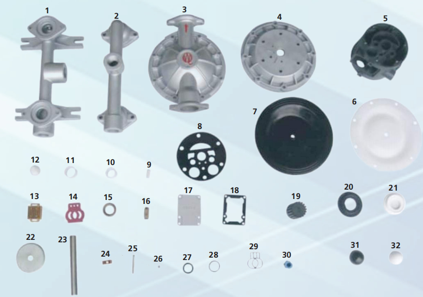
PART LIST
| No. | Name | Quantity | Material |
| 1 | Inlet pipe | 1 | Stainless steel, cast iron, aluminium alloy, plastic, inner lining FEP |
| 2 | Outlet pipe | 1 | Stainless steel, cast iron, aluminium alloy, plastic, inner lining FEP |
| 3 | Pump body | 2 | Stainless steel, cast iron, aluminium alloy, plastic, inner lining FEP |
| 4 | Pump chamber | 2 | Aluminium alloy, cast iron |
| 5 | Intermediate | 1 | Aluminium alloy |
| 6 | Diaphragm vane | 2 | PTFE |
| 7 | Diaphragm vane | 2 | Acrylonitrile butadiene rubber, polychloroprene |
| 8 | Intermediate seal gasket | 2 | Acrylonitrile butadiene rubber |
| 9 | Driving shaft housing | 2 | Plastic |
| 10 | Connecting rod shaft housing | 2 | Plastic |
| 11 | Piston bush | 2 | Plastic |
| 12 | Piston | 2 | Plastic |
| 13 | Slipper block | 1 | Aluminium alloy |
| 14 | Slipper block | 1 | Chromium-plated steel |
| 15 | Sealing slip ring | 1 | Plastic |
| 16 | Driving slipper block | 1 | Plastic |
| 17 | Cover plate | 1 | Aluminium alloy |
| 18 | Cover plate gasket | 1 | Rubber |
| 19 | Muffler | 1 | Plastic |
| 20 | Seal seat | 4 | Rubber |
| 21 | Seal seat | 4 | PTFE |
| 22 | Clamping bar | 4 | Stainless steel, carbon steel |
| 23 | Connecting rod | 1 | Stainless steel |
| 24 | Compression spring | 1 | Copper |
| 25 | Driving shaft | Stainless steel | |
| 26 | Seal ring of driving shaft | 2 | Rubber |
| 27 | Y-type O-ring | 4 | Rubber |
| 28 | O-ring | 1 | Rubber |
| 29 | Butterfly-type O-ring | 1 | Rubber |
| 30 | Inlet nozzle | 1 | Copper |
| 31 | Ball sealer | 4 | Rubber |
| 32 | Ball sealer | 4 | Stainless steel, ceramic, PTFE |
PART LIST
| Medium / Variety | Nitrile Rubber | Chloroprene Rubber | Fluorine Rubber | PTFE | Food Rubber |
| Smoke nitric acid | Х | Х | Δ | Δ | |
| Density nitric acid | Х | Х | Δ | Δ | |
| Density sulfuric acid | Х | Х | О | Δ | |
| Density hydrochloric acid | Х | Δ | Δ | Δ | |
| Density phosphoric acid | Х | Δ | Δ | Δ | |
| Density acetic acid | Х | Х | Х | Δ | |
| Density sodium hydroxide | О | О | Δ | Δ | |
| Non-aqueous ammonia | Δ | Δ | Δ | Δ | |
| Thin nitric acid | Х | Х | О | Δ | |
| Thin sulfuric acid | Δ | Δ | Δ | Δ | |
| Thin hydrochloric acid | Х | О | Δ | Δ | |
| Thin phosphoric acid | Х | Х | Δ | Δ | |
| Thin sodium hydroxide | О | О | Δ | Δ | |
| Liquid ammonia | Δ | Х | |||
| Benzene | Х | Х | О | О | |
| Gasoline | О | О | О | О | |
| Petroleum | Δ | Х | О | О | |
| Carbon tetrachloride | О | О | О | ||
| Carbon disulphite | О | Х | О | ||
| Alcohol | О | О | О | О | |
| Acetone | Х | Δ | Х | О | |
| Cresol | Х | Δ | Δ | О | |
| Acetic aldehyde | Х | Х | Δ | О | |
| Ethyl benzene | Х | Х | Δ | О | |
| Acrylonitrile | Δ | Δ | Х | О | |
| Butanol | О | О | О | О | |
| Butadience | О | Х | Δ | О | |
| Styrene | Х | Х | Δ | О | |
| Vinyl acetate resin | Х | Х | Х | О | |
| Ether | Х | Х | Х | О |